General Description
The evaluation board demonstrates the RT9527GQW to be designed for a fully integrated low cost single-cell Li-ion battery charger ideal for portable applications. The RT9527GQW optimizes the charging task by using a control algorithm, which includes pre-charge mode, fast-charge mode and constant voltage mode. The charging current is adjustable via an external resistor. It provides a wide fast-charge current setting from 10mA up to 600mA. The RT9527GQW features 28V maximum rating voltage for VIN and provides protection functions including undervoltage protection and overvoltage protection for the AC adapter supply. Besides, the internal thermal feedback circuitry regulates the die temperature to optimize the charge rate for all ambient temperatures.
Performance Specifications
The performance specificiaitons of RT9527GQW evaluation board are listed in Table 1. The test conditions are VIN = 5V, VBAT = 4V and TA = 25°C, unless otherwise specified.
Table 1. Performance Specifications of RT9527GQW Evaluation Board
|
Specification
|
Test Conditions
|
Min
|
Typ
|
Max
|
Unit
|
|
VIN Operating Range
|
|
4.4
|
--
|
6
|
V
|
|
VIN Undervoltage Lockout
Threshold
|
VIN = 0V to 5V
|
3.1
|
3.3
|
3.5
|
V
|
|
VIN Undervoltage Lockout
Hysteresis
|
VIN = 5V to 0V
|
--
|
240
|
--
|
mV
|
|
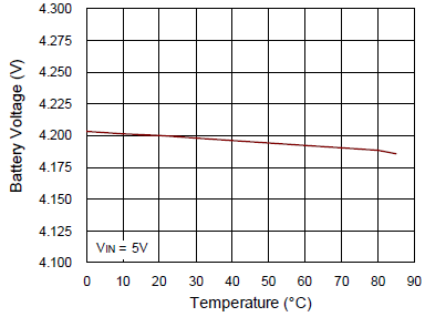
Battery Voltage Regulation
|
0°C to 85°C
|
4.158
|
4.2
|
4.242
|
V
|
|
Re-Charge Threshold
|
Battery Regulation – Recharge Level
|
60
|
100
|
140
|
mV
|
|
VIN Charging Setting Range
|
|
10
|
--
|
600
|
mA
|
|
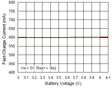
Fast-Charge Current Factor
|
ICHG_F1 = KCHG_F1 / RISET,
ICHG_F1 = 10mA to 50mA
|
510
|
600
|
690
|
AΩ
|
|
ICHG_F2 = KCHG_F2 / RISET,
ICHG_F2 = 50mA to 600mA
|
570
|
600
|
630
|
AΩ
|
|
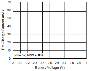
Pre-Charge Current Factor
|
ICHG_P = KCHG_P / RISET
|
30
|
60
|
90
|
AΩ
|
|
BAT Pre-Charge Threshold
|
VBAT falling
|
2.7
|
2.8
|
2.9
|
V
|
|
BAT Pre-Charge Threshold
Hysteresis
|
|
--
|
200
|
--
|
mV
|
|
Termination Current Ratio
|
VBAT > VPREC, ICHG < ITERMI,
 = L to H = L to H
|
5
|
10
|
15
|
%
|
|
Overvoltage Protection
|
|
6.2
|
6.5
|
6.8
|
V
|
|
Overvoltage Protect Hysteresis
|
|
--
|
0.2
|
--
|
V
|
|
ISET Pin Short Protection
|
|
375
|
500
|
625
|
Ω
|
|
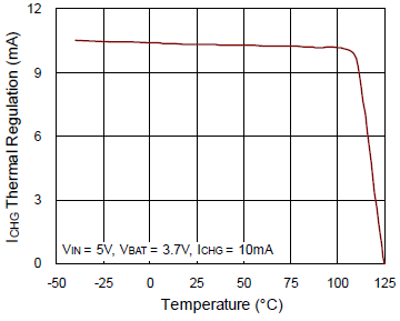
Thermal Regulation
|
|
--
|
125
|
--
|
°C
|
|
Pre-Charge Fault Time
|
CTIMER = 1μF
|
1440
|
1800
|
2160
|
s
|
|
Fast-Charge Fault Time
|
CTIMER = 1μF
|
11520
|
14400
|
17280
|
s
|
Power-up Procedure
Required Equipment
- RT9527GQW evaluation board
- DC power supply
- Electronic load
- Multimeter
- Oscilloscope
Quick Test Procedures
Inspect all the components on the EVB and make sure they are undamaged. Do not turn on power supplies until they are connetced well on the EVB.
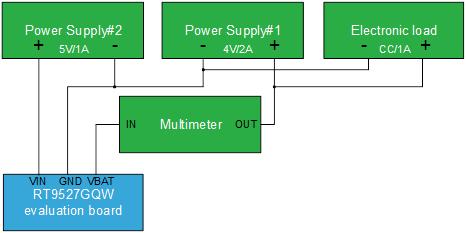
Equipment setup and the test procedures are stated below:
1) Set power supply#1 voltage = 4V and current = 2A and connect it to VBAT pin through meter and GND pin on the EVB.
2) Connect an e-load with power supply#1 in parallel and sink 1A in CC mode.
3) Set power supply#2 voltage = 5V and current = 1A and connect it to VIN and GND pins on the EVB.
4) Turn on power supply#1 and the electronic load.
5) Turn on power supply#2.
6) Check whether LED1 and LED2 light or not.
7) Use a multimeter to check whether IBAT equals to KCHG_Fx / RISET or not.
Test Environment Diagram
Detailed Description of Hardware
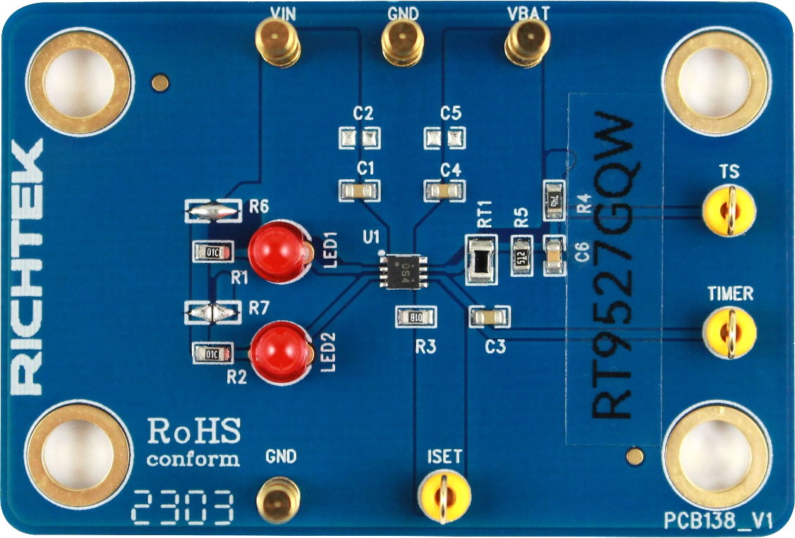
Headers Description and Placement
Carefully inspect all the components used in the EVB according to the following Bill of Materials table, and then make sure all the components are undamaged and correctly installed. If there is any missing or damaged component, which may occur during transportation, please contact our distributors or e-mail us at evb_service@richtek.com.
Test Points
Test points are provided on the EVB and their pin names are listed in the table as shown below.
|
Test Point/
Pin Name
|
Pin Function
|
|
VIN
|
Supply voltage input.
|
|
VBAT
|
Charge current output for battery.
|
|
GND
|
Ground.
|
|
TS
|
Battery temperature sense input.
|
|
TIMER
|
Safe-charge timer setting.
|
|
ISET
|
Charge current setting.
|
Bill of Material
|
Reference
|
Count
|
Part Number
|
Value
|
Description
|
Package
|
Manufacturer
|
|
U1
|
1
|
RT9527GQW
|
RT9527GQW
|
Single Cell Li-Ion Battery Charger
|
WDFN-8L 2x2
|
RICHTEK
|
|
C1, C3, C4
|
3
|
0603X105K250CT
|
1µF
|
Ceramic Capacitor, 25V/X5R
|
0603
|
WALSIN
|
|
C2, C5
|
2
|
--
|
NC
|
--
|
--
|
--
|
|
C6
|
1
|
0603B102K500CT
|
1nF
|
Ceramic Capacitor, 50V/X7R
|
0603
|
WALSIN
|
|
R1, R2
|
2
|
WR06X1002FTL
|
10k
|
Chip Resistor, 1/10W, 1%
|
0603
|
WALSIN
|
|
R3
|
1
|
WR06X1001FTL
|
1k
|
Chip Resistor, 1/10W, 1%
|
0603
|
WALSIN
|
|
R4
|
1
|
RTT035761FTP
|
5.76k
|
Chip Resistor, 1/10W, 1%
|
0603
|
RALEC
|
|
R5
|
1
|
RC0603FR-075K1L
|
5.1k
|
Chip Resistor, 1/10W, 1%
|
0603
|
YAGEO
|
|
LED1, LED2
|
2
|
LNL-302RD000A1
|
RED
|
LED
|
DIP
|
LighTop
|
|
RT1
|
1
|
NCP21XH103F03RC
|
10k
|
Chip Resistor, NTC
|
0805
|
MURATA
|
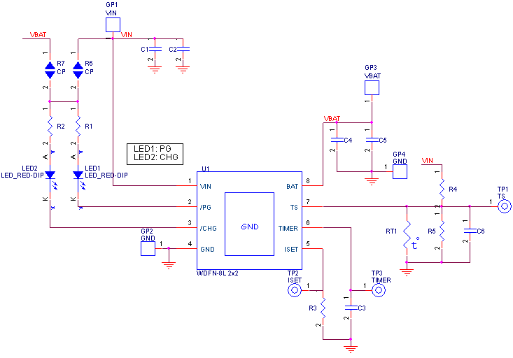
Typical Applications
EVB Schematic Diagram
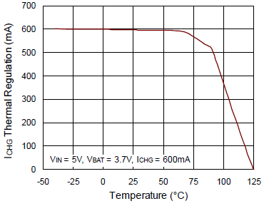
Measurement Result
|
Charge Current (ICHG = 600mA) vs. Temperature
|
Charge Current (ICHG = 10mA) vs. Temperature
|
|
|
|
|
Pre-charge Current vs. Battery Voltage
|
Fast-charge Current vs. Battery Voltage
|
|
|
|
|
Battery Regulation Voltage v.s. Temperature
|
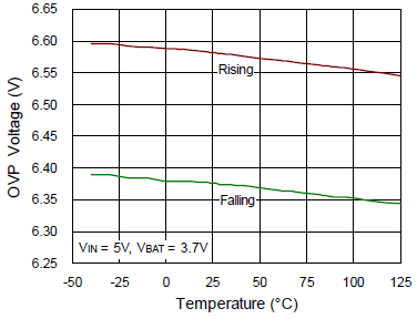
OVP Threshold Voltage vs. Temperature
|
|
|
|
|
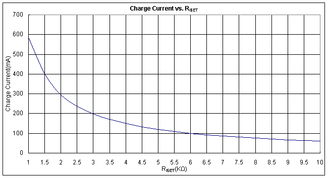
Charge Current vs. RISET
|
|
|
|
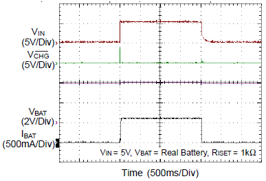
Charge On/Off Control from VIN
|
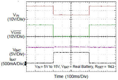
VIN Overvoltage Protection
|
|
|
|
|
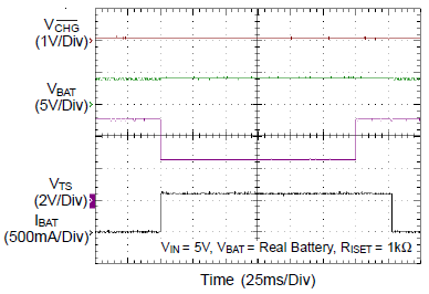
TS Inserted/Removed
|
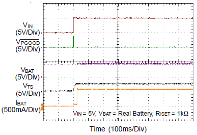
VIN Hot-Plug with Battery and NTC
|
|
|
|
Evaluation Board Layout
The layout of RT9527GQW evaluation board is shown in Figure 1 and Figure 2. It is a two-layer PCB with 1 oz. Cu coated on both top and bottom sides and the PCB size is 70mm x 50mm.
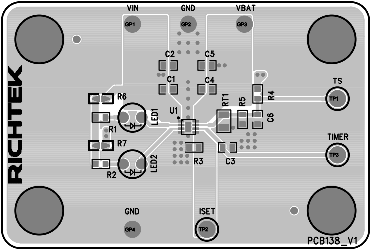
Figure 1. Top View (1st layer)
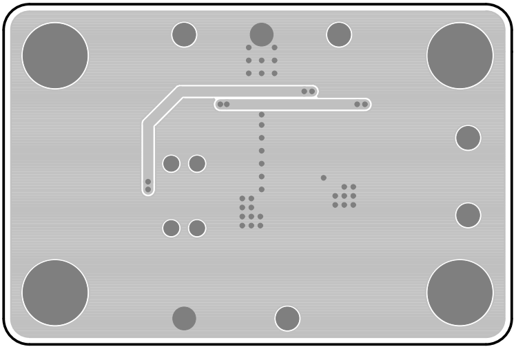
Figure 2. Bottom View (2nd layer)